|
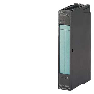
SIMATIC DP, 5 ELECTRON. MODULES FOR ET 200S, 2 DO HIGH FEATURE 24V DC, 15 MM WIDTH DIAGNOSIS F. SHORT-CIRCUIT AND OPEN-CIRCUIT, FIRST-UP SIGNAL WITH LED SF (GROUP FAULT), 5 PIECES PER PACKAGING UNIT |
| Supply voltage |
| Reverse voltage protection |
Yes; when using the same load voltage as on the power module |
| Load voltage L+ |
| ● Rated value (DC) |
24 V; From power module |
| ● Reverse polarity protection |
Yes; polarity reversal can lead to the digital outputs being connected through |
| Input current |
| from load voltage L+ (without load), max. |
5 mA; Per channel |
| from backplane bus 3.3 V DC, max. |
10 mA |
| Power loss |
| Power loss, typ. |
0.4 W |
| Address area |
| Address space per module |
| ● with packing |
2 bit |
| ● without packing |
1 byte |
| Digital outputs |
| Number of digital outputs |
2 |
| Short-circuit protection |
Yes |
| ● Response threshold, typ. |
1,5 A |
| Limitation of inductive shutdown voltage to |
-55 to -60 V, typ. L+( ) |
| Controlling a digital input |
Yes |
| Switching capacity of the outputs |
| ● Lamp load, max. |
2.5 W |
| Load resistance range |
| ● lower limit |
48 Ω |
| ● upper limit |
3 400 Ω |
| Output voltage |
| ● for signal "1", min. |
L+ (-1 V) |
| Output current |
| ● for signal "1" rated value |
0.5 A |
| ● for signal "1" permissible range for 0 to 60 °C, min. |
7 mA |
| ● for signal "1" permissible range for 0 to 60 °C, max. |
600 mA |
| ● for signal "0" residual current, max. |
0.3 mA |
| Output delay with resistive load |
| ● "0" to "1", max. |
100 µs |
| ● "1" to "0", max. |
400 µs |
| Parallel switching of 2 outputs |
| ● for uprating |
No |
| ● for redundant control of a load |
Yes; per module |
| Switching frequency |
| ● with resistive load, max. |
100 Hz |
| ● with inductive load, max. |
2 Hz |
| ● on lamp load, max. |
10 Hz |
| Total current of the outputs (per group) |
| all mounting positions |
| — up to 60 °C, max. |
1 A |
| Cable length |
| ● Cable length, shielded, max. |
1 000 m |
| ● Cable length unshielded, max. |
600 m |
| Isochronous mode |
| Isochronous mode (application synchronized up to terminal) |
Yes |
| Interrupts/diagnostics/status information |
| Substitute values connectable |
Yes; 0/1 |
| Diagnostic messages |
| ● Diagnostic functions |
Yes; Can be read out |
| ● Wire-break |
Yes; channel by channel |
| ● Short-circuit |
Yes; channel by channel |
| Diagnostics indication LED |
| ● Group error SF (red) |
Yes |
| ● Status indicator digital output (green) |
Yes |
| Parameter |
| Remark |
3 byte |
| Diagnostics wire break |
Disable / enable |
| Diagnostics short-circuit |
Disable / enable |
| Behavior on CPU/master STOP, channel-wise |
Substitute a value/keep last value |
| Galvanic isolation |
| Galvanic isolation digital outputs |
| ● between the channels |
No |
| ● between the channels and the backplane bus |
Yes |
| Isolation |
| Isolation tested with |
500 V DC |
| Dimensions |
| Width |
15 mm |
| Height |
81 mm |
| Depth |
52 mm |
| Weights |
| Weight, approx. |
40 g |
| last modified: |
21.08.2014 |